Table of Contents
Pinout
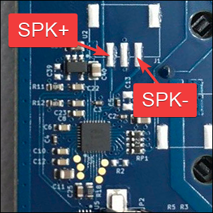
Both versions have a similar layout for the pins you need to use. In the H1, the connector might not be populated and look like this:
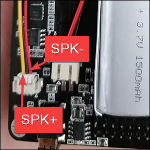
On the H2, normally the connector and cable (use the red and yellow wires, isolate the black one) is included as seen here:
For both versions, you need a small speaker. Typically a laptop speaker will work, for example: https://a.aliexpress.com/_mLuZk4U
Connect SPK+ and SPK- to the speaker and use double sided tape to fix it to the PCB.
Speaker test: https://www.youtube.com/watch?v=XkaGV9muvbg
Additional details
A speaker has two wires, SPK+ and SPK-. While there is no sound, the speaker floats on a magnetic field in the middle of its range. When SPK+ is high the speaker moves forward. When SPK- is high the speaker moves backwards. The distance forward and backwards depends entirely on the voltage level.
On the PortaPack, the speaker connector has 3 pins.
SPK+ is the pin nearest to the edge of the board
GND is the connector in the middle, skip it
SPK- is towards the centre of the board
H1 specific setup
On the H1 with an AK4951 codec, when you add the new speaker you may find that there is no audio. In this case, use the speaker icon on the title bar to enable the speaker output (grey with "X" indicates muted; green with no "X" indicates it's unmuted).
Warning: Do not set the speaker icon to "unmuted" if the speaker already works when "muted", as on one model of the OpenSourceSDRLab PortaPack H2 which has two audio chips with their outputs tied together (overheating will result if they're both enabled).
This file contains Unicode characters that might be confused with other characters. If you think that this is intentional, you can safely ignore this warning. Use the Escape button to reveal them.
How to collaborate
How to ask questions correctly
User manual
- First steps
- Usage cautions
- Intended use and Legality
- Features
- PortaPack Versions (which one to buy)
- HackRF Versions
- Firmware update procedure
- Description of the hardware
- User interface
- Powering the PortaPack
- Troubleshooting
- Won't boot
- Config Menu
- Firmware upgrade
- Diagnose firmware update in Windows
- Receive Quality Issues
- No TX/RX
- TX Carrier Only
- H2+ speaker modifications
- Dead Coin Cell Battery
- Factory Defaults
- SD card not recognized by PC with the SD-card over USB selected
- DFU overlay
- Full reset
- SolveBoard
- How to Format SDCard
- What if I don't like some of the apps
- Applications
Misc
Developer Manual
- Compilation of the firmware
- Compile on WSL with ninja
- How to compile on Windows faster with WSL 2
- Using Docker and Kitematic
- Docker command-line reference
- Using Buddyworks and other CI platforms
- Notes for Buddy.Works (and other CI platforms)
- Using ARM on Debian host
- All in one script for ARM on Debian host
- Compile on Arch based distro (exclude Asahi)
- Dev build versions
- Notes About ccache
- Create a custom map
- Code formatting
- PR process
- Description of the Structure
- Software Dev Guides
- Tools
- Research
- UI Screenshots
- Maintaining
- Creating a prod/stable release (Maintainers only)
- Maintaining rules
- Development States Notes
Hardware Hacks
Note
The wiki is incomplete. Please add content and collaborate.
Important
- This is a public wiki. Everything is visible to everyone. Don't use it for personal notes.
- Avoid linking to external tutorials/articles; they may become outdated or contain false information.

